You of course will need to access the valve covers and remove them and set aside.
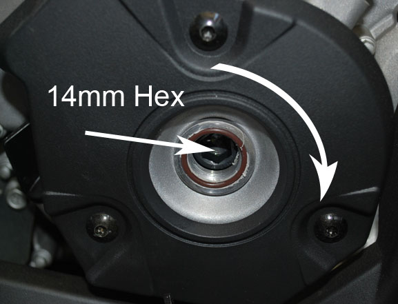
Here we see the flywheel bolt and for this we will be turning in a clockwise rotation to get to both the #1 timing mark and #2 timing mark.
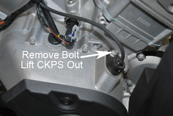
Remove the 6mm bolt (8mm head) and using a gasket scraper or even the tool to remove the plastic push rivets for the body work and get under and lift slightly as there is sealant as well as a o-ring holding the crank position sensor in.
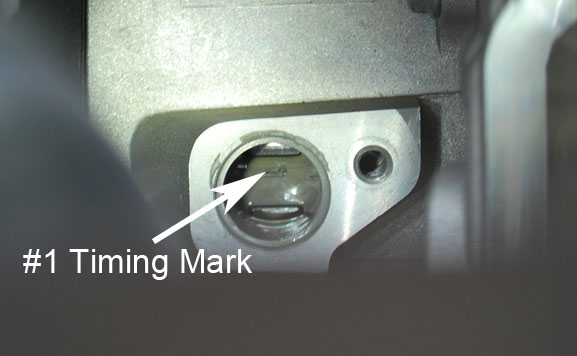
After turning you see the #1 timing mark in the window and have the mark line up with the middle of the window.
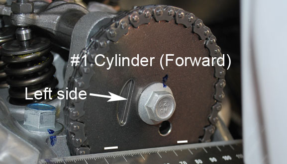
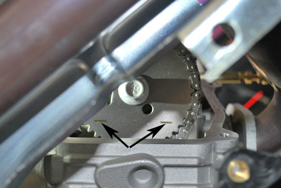
Now looking at the #1 cam sprocket we see the lines are lined up parallel to the surface of the head.
So this is showing us that the cam is in time with #1 piston location and ready to set the valve lash on.
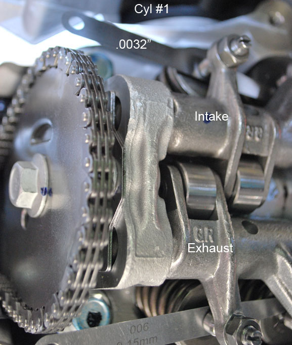
The valve lash specs are as follows, All Models Intake = .05mm-.09mm (.002"-.0035") Exhaust = .10mm-.15mm (.004"-.006").
Adjust until you have a slight drag on the feeler gauge blade with locknut tight (8.85 lbs/ft) so not very tight.
Check the clearances first to decide whether they need to be adjusted or not, If not move to next.
If you have to adjust them use a 10mm wrench (open end works fine) and loosen jam nut.
Using a short flat tip screwdriver back off the adjusting screw slightly and insert the appropriate feeler gauge and tighten up on the adjusting screw until you feel a slight drag on the blade.
Cinch down on the jam nut lightly and check your drag again, If it is ok then on to the next and if not repeat process until you have that slight drag. Torque lock nut to 8.85 lbs/ft.
Here I have the blades inserted between the tip of the valve and the rocker with .0032" on Intake & .006" Exhaust, I have found that the exhaust tends to close up at the service intervals so I adjust to the max spec on exhaust.
When you have completed cylinder #1 then move on to cylinder #2.
Rotate the engine in a clockwise rotation until we see timing mark #2 line up with the middle of the crank position sensor hole.
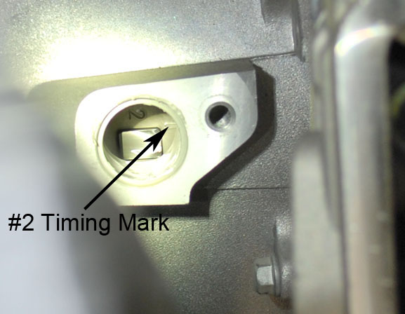
We can see that #2 cam is also in time with the piston location on cylinder #2 so you are ready to set the valve lash on #2.
After all is completed re-install everything that was removed to accomplish this task.