It is a very simple procedure to check cam timing and even correct it if needed and in this instance I did not remove the spark plugs and it just adds a bit more resistance when turning.
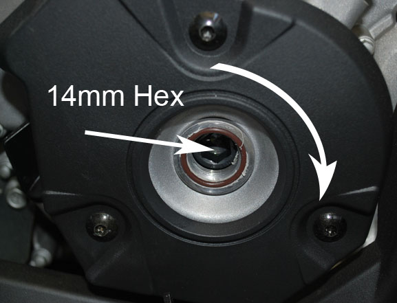
You will need to remove this plug on the right side of the engine to access the flywheel bolt.
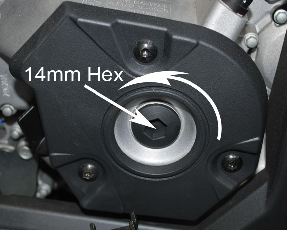
Here we see the flywheel bolt and for this we will be turning in a clockwise rotation to get to both the #1 timing mark and #2 timing mark.
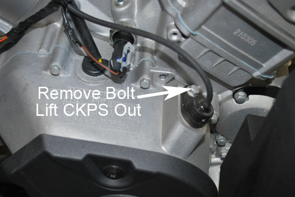
Remove the 6mm bolt (8mm head) and using a gasket scraper or even the tool to remove the plastic push rivets for the body work and get under and lift slightly as there is sealant as well as a o-ring holding the crank position sensor in.
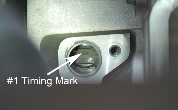
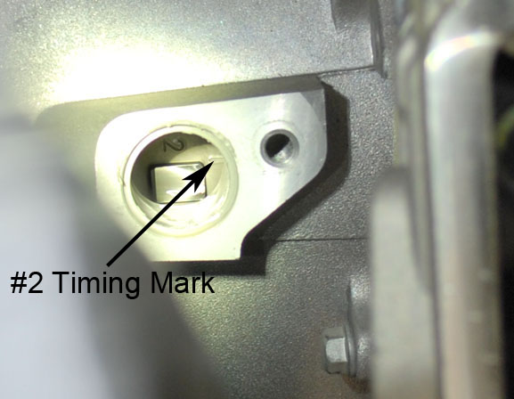
After turning you see the #1 timing mark in the window and have the mark line up with the middle of the window.
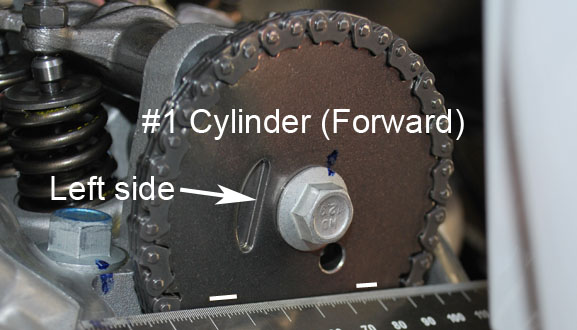
Now looking at the #1 cam sprocket we see the lines are lined up parallel to the surface of the head.
So this is showing us that the cam is in time with #1 piston location.
Now we move on to #2 so we rotate the engine in a clockwise rotation until we see timing mark #2 line up with the middle of the crank position sensor hole.
In this case we can see that #2 cam is also in time with the piston location on cylinder #2.
Adjustment Section:
While this may not be as detailed as some of you may like the process is very simple as all we are really doing here is making sure the cam is timed correctly with the crank.
With the first section read and performed we either have a engine that the cam timing is correct or it isn't, We are going to assume in this case it was not in time so you can get an idea of how to correct it.
Since we are showing cylinder #1 below we want the timing mark lined up correctly in the crank position sensor bore. As shown below.
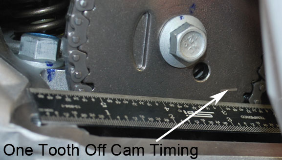
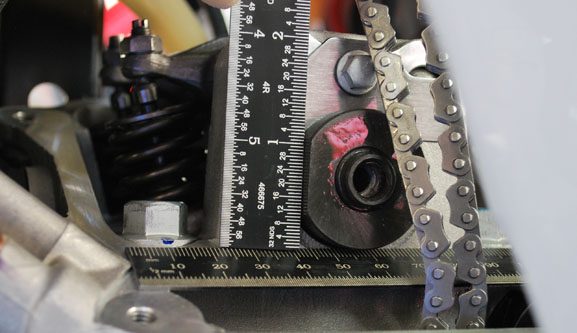
In this image you can see that the cam timing marks are not inline with the 6" machinist scale resting across the machined surface where the valve cover sits. So we are one tooth off.
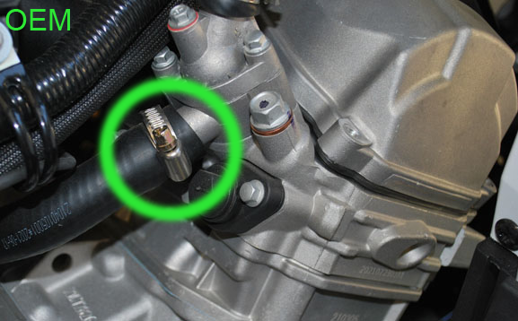
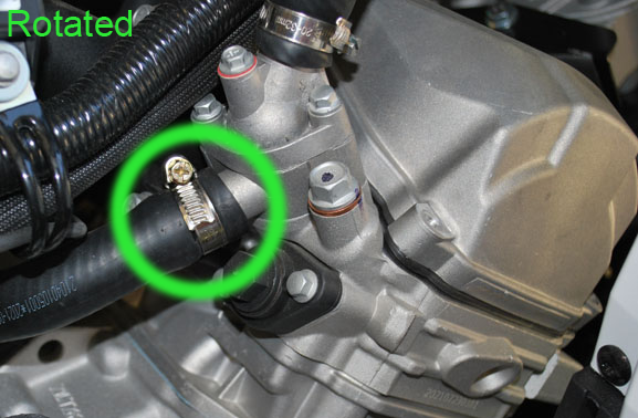
You will need to remove this clamp and flip and rotate as oem has it in direct path of the cam tensioner cap.
This after rotation and now cap is clear for removal.
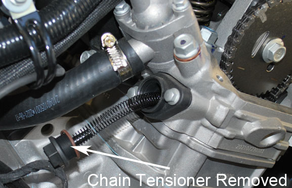
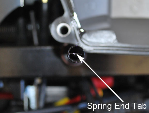
Using a 15mm open end wrench just remove cap (ccw rotation) and just pull cap and spring out and set aside.
The cap has a slot to place the end of the spring in and the spring has tabs both ends as shown in the next image.
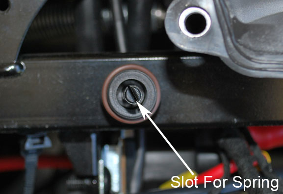
The spring has the tabs on both ends as when you install the cap with the spring properly located in the sleeve and on the cap it will create a torsion force when installed and that in turns turns the sleeve that is on a cam and will tighten as the chain loosens. So theoretically you always have cam chain tension.
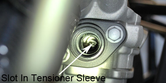
You will need to insert a flat blade screwdriver in the slot shown in the sleeve and turn counter clockwise and please just use two fingers on the screwdriver as it will back out and give you slack in the cam chain.
No hamfisting this, When it stops stop turning.
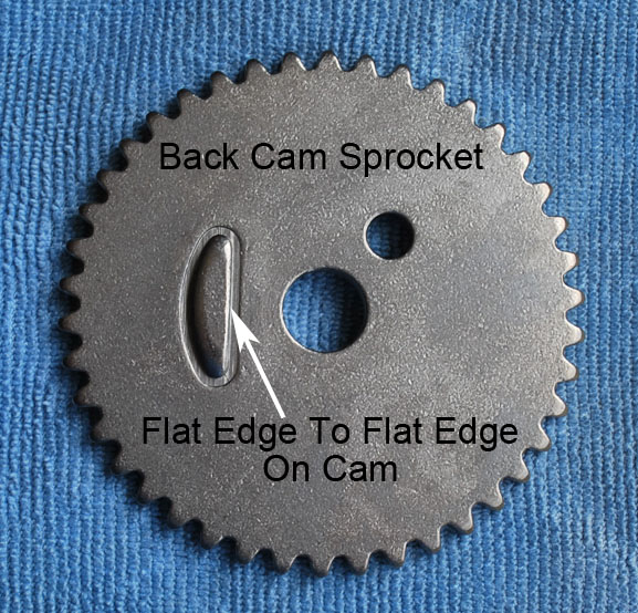
After removing the cam sprocket by loosening the 13mm hex head bolt (CCW) you can pull the cam sprocket and you will notice that the back has a raised edge to locate against the flat on the camshaft.
Just showing the flat on the cam itself and you will notice that when the cam is at TDC the flat will be on the left side as you are looking at it.
Notice the flat is 90° to the horizontal surface which means the cam is located exactly where it should be so it is in time. This may rotate a but unless you use the tool from CanAm to hold it.
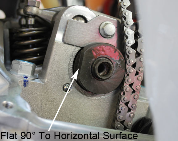
Since I don't have the tool for holding it I am just going to show you how it would look using 2 6" machinist scales.
So basically a upside down T and that is where the cam should be.
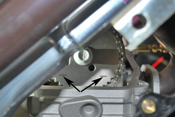
It is a pain to keep track of how many teeth it may be out so regardless of how many it is off mark the chain and sprocket so you have a reference.
In the white circle you will see the black line which is the mark for when I was one tooth off and it WAS lined up with the grey mark on the chain.
Now with it corrected grey is lined up with grey and the cam is in time.

Once you have it set where you think is correct with the flat bladed screwdriver screw the sleeve in until there is no further back and forth on the cam sprocket then add another 1/8 turn and that will set the tensioner at proper tension.
Now take the spring and cap and place in the sleeve and turn (CW only) until you can feel a slight resistance on the turning and then push cap in and screw in to block. No hamfisting here as it just needs to be snug and the o-ring will take care of the sealing. (No need to preload spring and only turn in a clockwise direction or the sleeve will back out).
Now rotate engine at flywheel returning to the "1" in the crank position window and then turn another complete revolution coming back to "1" again and everything should line up as it is supposed to, If not then readjust and if so then pull the bolt back out of the cam sprocket and apply some medium thread locker and torque to 22.14 lbs/ft.
Setting #2 Cam Timing:
To set the timing on Cyl#2 turn the flywheel in the clockwise direction and stopping when you see the line for #2 cyl line up with middle of crank position sensor bore. If it is correct you will see the two marks on the #2 cam sprocket horizontal with the machined surface where the valve cover sits.
Note: Please make sure to turn the engine over by HAND 4 full revolutions to make sure there is no interference.
If there is any interference please stop and back up and find the cause before hitting that starter button or turning the key.