Since purchasing this machine and initially after the test drive I always had thought the the suspension was stiffer then it needed to be, Stiffness can come from different sources being valved too stiff is of course one but it can also come from being valved too soft on compression and rebound too slow as well as higher then desired spring rates. Since the OEM shock is only preload adjustable and lacks any rebound or compression damping adjustments one must go inside the shock to address the issues.
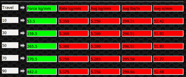
Front Spring: Not too bad as it is the correct spring rate (300 lbs/in) and it is a linear rate spring. Looking at the table below you can see the various rates at different deflection points.
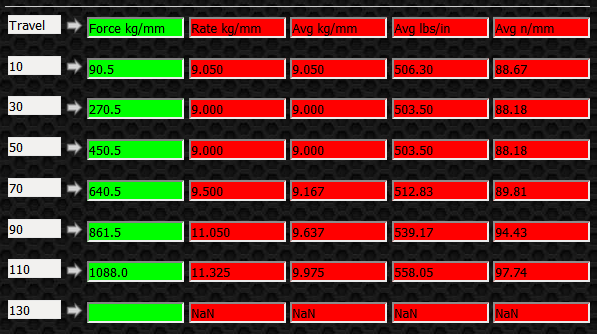
Rear Spring: The rear spring is a progressive spring and you can see in the table below the various rates at the measured deflection points. I would rather see a linear rate 400 lb/in spring as opposed to the OEM progressive.
Before performing any servicing of any Nitrogen pressurized shock Make Sure All Nitrogen Has Been Released.If you are NOT familiar with suspension work or just don't feel comfortable working on suspension STOP and send it to a suspension specialist.
Seal Head Retaining Clip: Remove the body cap and push down on seal head and clip will be exposed. Using a clip removing tool push the clip down and then guide it up out of the main body. Then it will take some effort but wrap a shop towel or some shop rags around the body where the seal head is going to come out and rock back and forth while pulling the shaft up out of the body. DON'T get any ideas that you will just use air pressure to pressurize the chamber and shoot it out of there, The shaft assembly will turn into a missile and you will have oil everywhere.
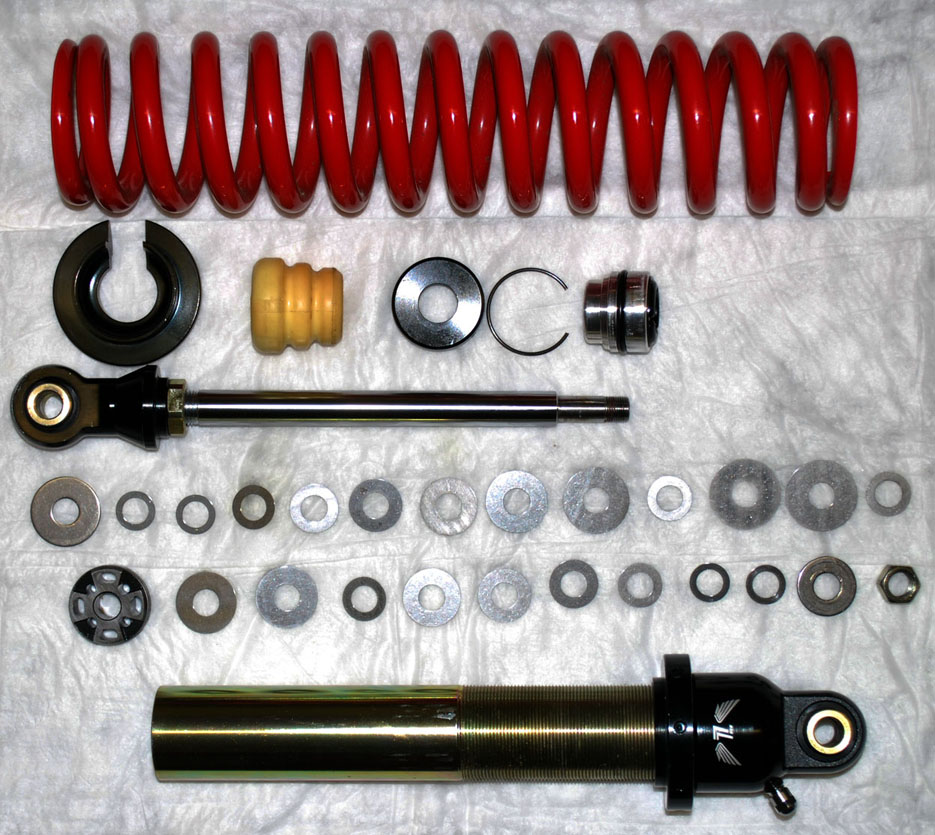
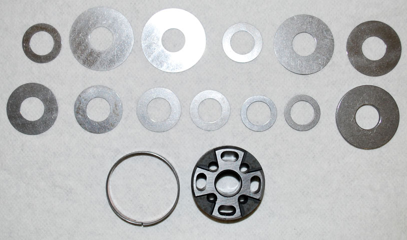
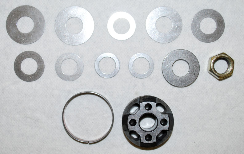
Disassembled Shock: Once the above step is completed and all the parts taken down as far as you will need it will look something like the image below. The nut holding on the valving is a 17mm and has red loctite on the threads so it will take a little effort to break that loose. DO NOT use heat on the nut as the shims are thin heat treated steel and they need to keep there temper.
Compression Stack and Piston Face: Notice the smaller diameter shim top left, That is what I call a float shim in that it holds the face shim away from the sealing surface of the piston itself and allows flow on the compression stroke without any shim deflection. Makes for very little compression damping at lo speed compression. Lo speed meaning shaft velocity not vehicle speed. If you are going inside the shock remove that shim and it will stiffen up the lo speed compression.
Notice the smaller od shim top row fourth from the left, That is a crossover shim and makes the lo speed compression just a bit faster then when the face shims touch the shim below the crossover then you are in the hi speed damping section of the shim stack.
Rebound Stack and Piston Face: Notice the smaller od shim top row third from the left, That is a crossover shim and makes the lo speed rebound just a bit faster then when the face shims touch the shim below the crossover then you are in the hi speed damping section of the shim stack.
Bleed location: This bleed size was a 1.0mm bleed but have changed that to a 1.3mm bleed. A 1.0 (OEM) bleed is too small IMO as the shock does not have a rebound adjuster and normally when adjusted the rebound would flow more through the adjuster then a 1.0mm bleed would allow. Also keep in mind even though we are increasing the bleed size we removed the float shim to give it more compression damping.
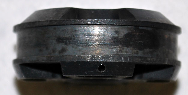
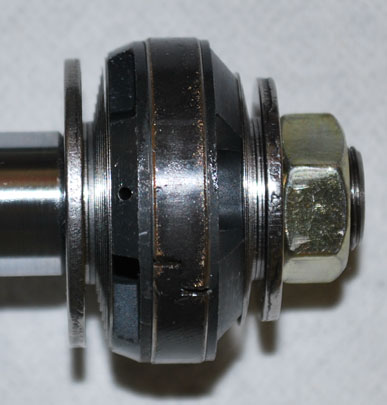
Correct Assembly of Compression stack, Piston, Rebound stack: Notice where the 1.3mm bleed is located. This is how your shock stack and piston assembly should look if assembled correctly. When you put the nut on put a bit of Loctite (271) Hi-Temp / Hi Strength thread locker on the threads and tighten to 25 lbs/ft. Make sure piston is not able to rotate after tightening. If you can rotate the piston you don't have a tall enough stack /piston combination and will need to add spacers shims. Spacer shims are any shim larger then the clamp shim.
Read Carefully!! Correct Quantity of Shock Fluid: In an emulsion design shock make absolutely certain you are using the correct amount of fluid. Overfilling of any shock for that matter may cause the shock to explode so take the time and make sure it is 100% correct. This is not one of those fill it to the top and install the shaft assembly, That would lead to hydraulic locking the shock and when the shaft is compressing that internal pressure has to go somewhere.
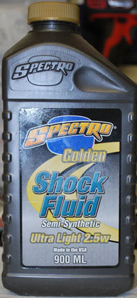
Use a Good Quality Shock Fluid: Use the best fluid you can find as it doesn't take that much fluid to service all (4) shocks and the higher the VI the better. Make sure it is for Shock and not forks as forks do not develop the heat that a shock will.
If you are not a suspension person but you have questions feel free to ask as that is the only way we gain knowledge.
Here are the specs for the OEM front /rear shocks:
Body ID = 36mm
Shaft OD = 16mm
Shaft Travel = 129mm
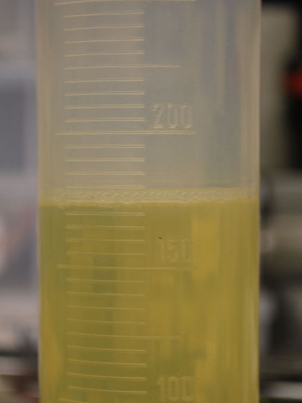
Fluid Quantity = 175cc
Fluid Viscosity = 2.5wt
Nitrogen Press = 200psi
Spring free length front = 339mm
Spring free length rear = 350mm
Spring installed (OEM) length front = 317mm
Spring installed (OEM) length rear = 327mm
OEM Preload front = 22mm
OEM Preload rear = 23mm
Compression shim stack front / rear:
20x.10 Float Shim
(2)32x.15 Face Shim
20x.20 Crossover Shim
30x.20
28x.20
26x.20
24x.20
22x.20
20x.20
(2)18x.47 Clamp Shim
32x2.04 Base Washer
Rebound shim stack:
(2)28x.20 Face Shim
20x.10 Crossover Shim
26x.20
24x.20
22x.20
20x.20
(2)18x.47 Clamp Shim
27x2.0 Base Washer